|
|
|
|
20H Conversion kit instructions
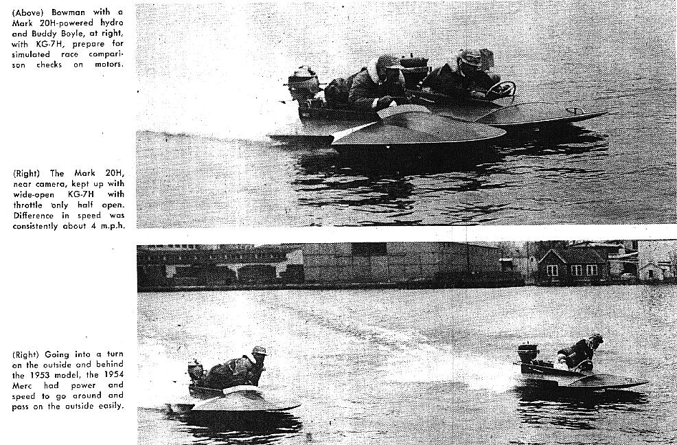
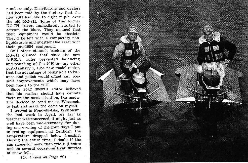
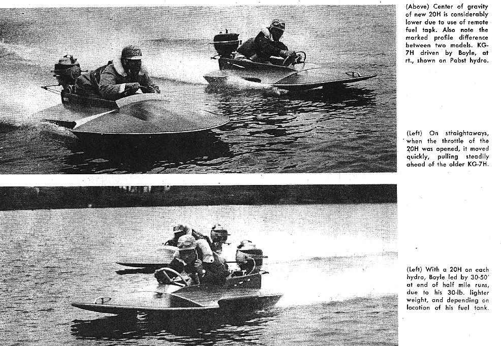
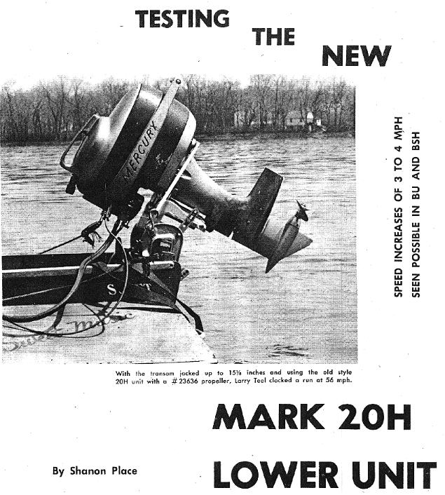
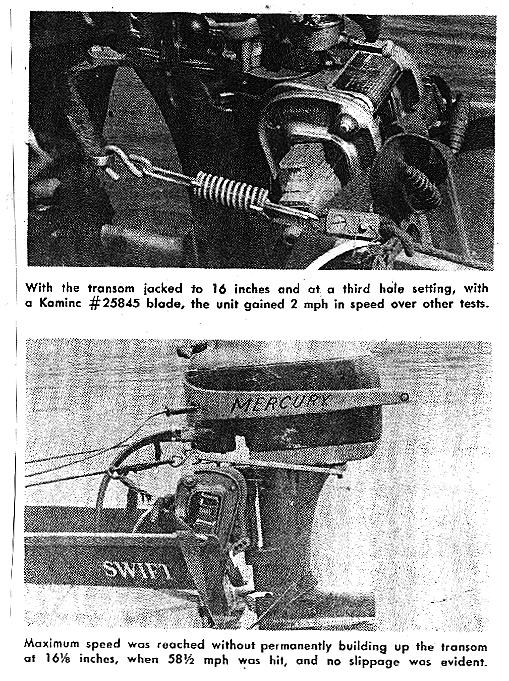
BOAT SPORT ARTICLE ON TESTING THE "NEW" 20H MERC
BOAT SPORT ARTICLE ON TESTING THE "NEW" 1956 LONG SKEG 20H UNIT
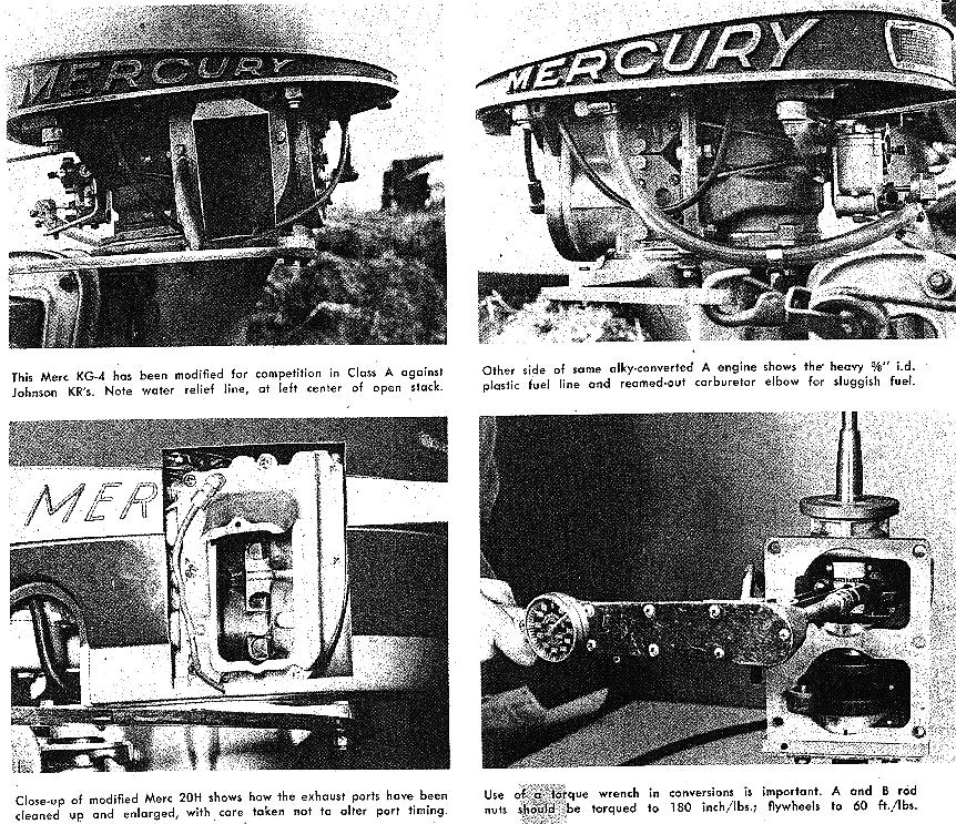
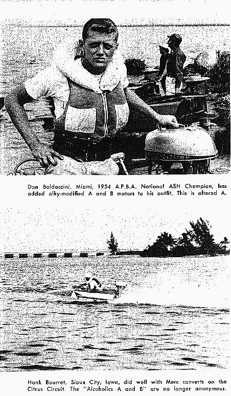
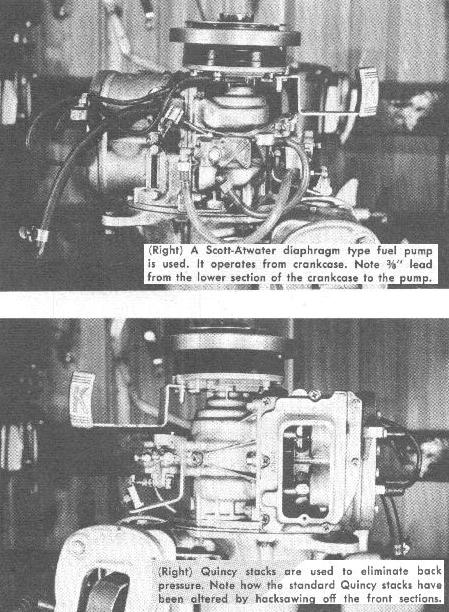
MODIFYING A MERC TO RUN ON ALKY
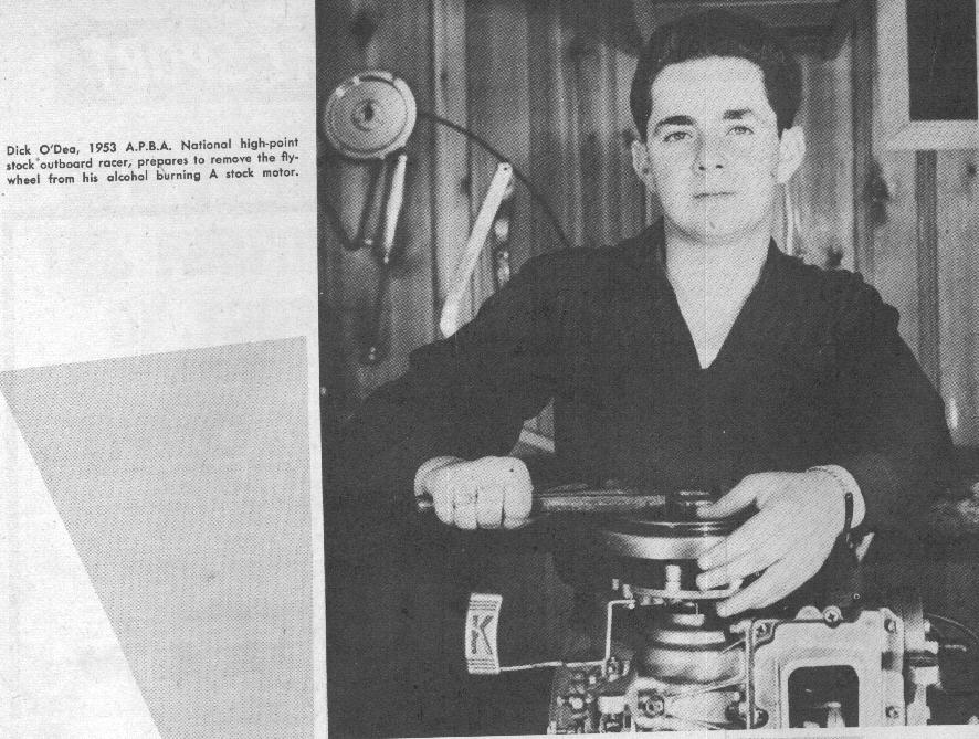
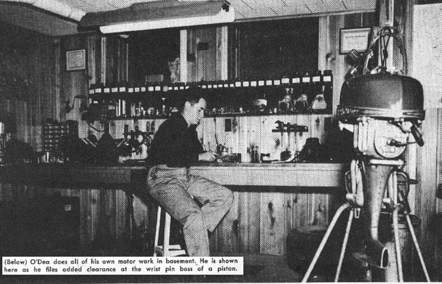
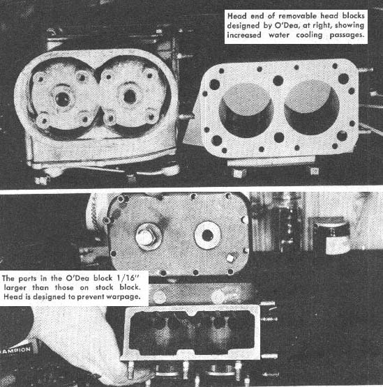
DICK O'DAY's HIGH SPEED SECRETS AND MODS
PEP HUBBELL'S ALKY VS. GAS MODS
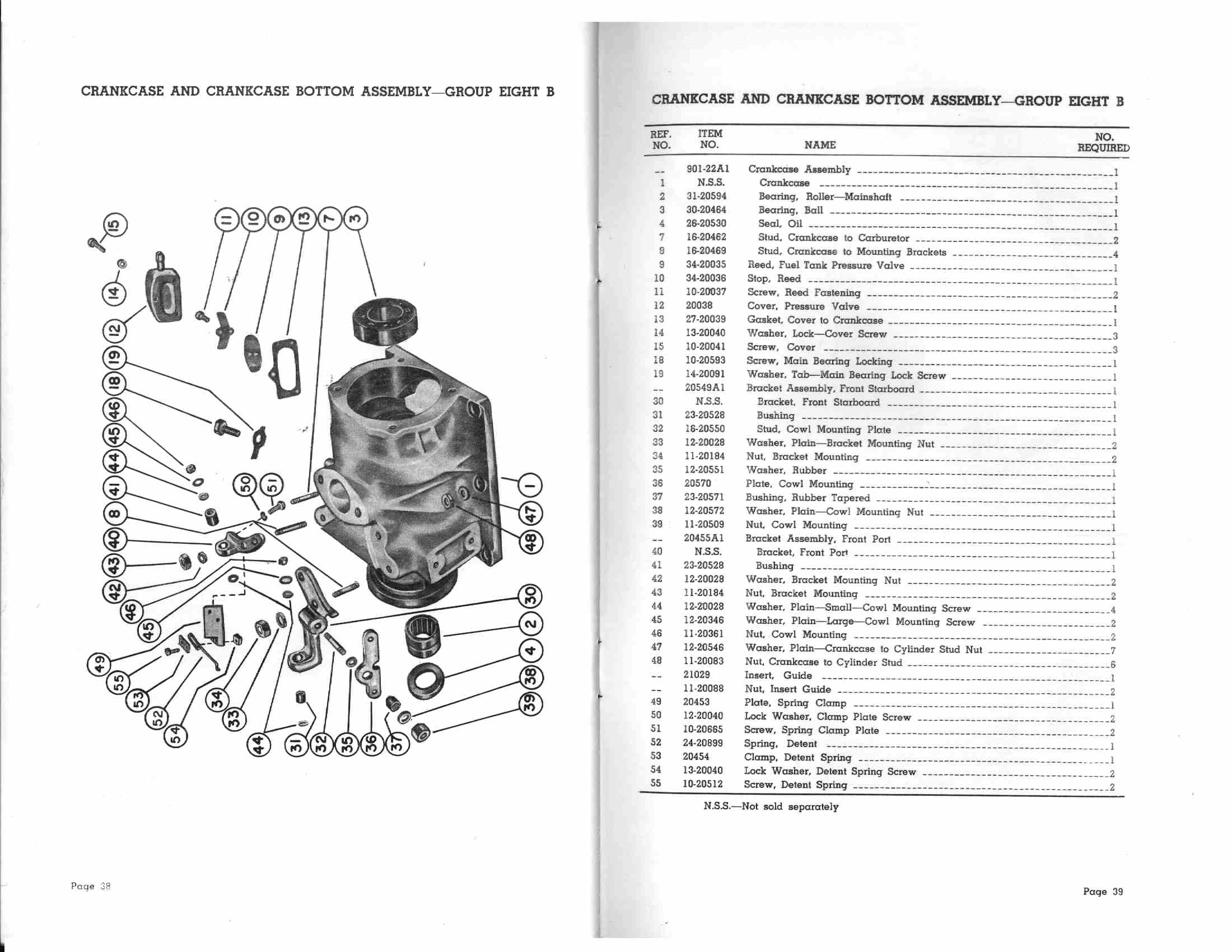
BLUEPRINTING THE 20H The 1954 Mercury Mark 20H Stock Closed Exhaust Blueprinting and Machining Specifications by Machinist and Club Member, Mike Petty CRANKCASE WORK: First completely disassemble the complete motor including all needle bearings, ball bearings and seals. Step One: press upper ball bearing (old one) back into the crankcase. Install the crankshaft without the reed cage. Now install the lower ball bearing and crankcase section and snug tight. Take a 0-1" depth micrometer, check the top dead center on the top of the stroke of #1 and #2 pistons to compare to each other to show if the crankcase is flat at the gasket surface. If #1 or #2 are within .005 place crankcase on a milling machine with the carb hole facing up, clamp and fly cut carb hole with studs removed to minimum clean up. After this operation, flip the crankcase over and cut the main crankcase gasket surface with the fly cutter big enough to cover in one pass to clean-up 100%. Example: My crankcase took .006 to clean up. Now recheck #1and #2 at TDC again with a depth micrometer as before and they should read the same the closer the better. Do not worry too much about the side- to side reading as you are more concerned about the top to bottom readings. After fly cutting the gasket surface, re-countersink all stud holes and check in the carb throat for burrs, nicks and smooth entry from the crankcase to the reed block. Now is a good time to countersink the reed block main bolt hole so it will not scratch the case while installing. Run all threads with the proper size taps and install heli-coils as-needed.
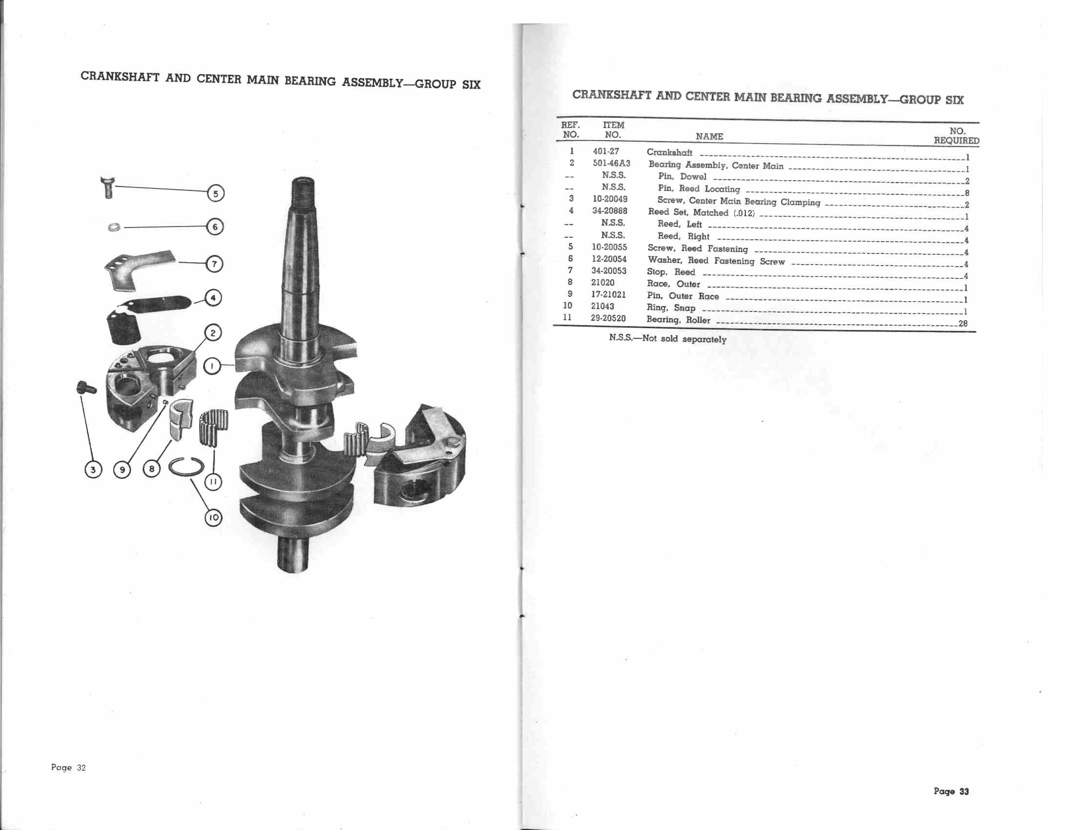
CRANKSHAFT INSPECTION: First mic all surfaces and compare to the stated Mercury tolerances. On this my crank was perfect and was in like new condition. Over to the lay out table (granite) I put the crankshaft in two machinist's V blocks on the ball bearing surfaces top and bottom. Take the height gauge with needle indicator and check the top of all bearing surfaces and rotate the crank at each surface to check for the amount of run out, dips or flat spots. I had none and run out was at .0002 at the center bearing. Now to check the stroke, rotate the cranks until # 1 throw is at TDC then take your height gauge and set the indicator needle on 0 reading as you rock the crank back and forth to get the highest reading. Now take the height gauge off of # 1 and rotate the crank 180 degrees to TDC of the # 2 throw and move the height gauge in slowly rocking the crank back and forth again to see how close to zero # 2 is. Example: My crank was .0015 different, not perfect but within tolerances. I will not be checking the INDEX of the crank because if it is off again there is no changing it as it has to be where it is at this point.
BALANCING OF THE ROTATING ASSEMBLY: As I feel this motor
will perhaps operate in the 8200 RPM range the type of balance Job I have picked is 1950's
technology but I feel that this is what is necessary and is much better than leaving the
crank, rods, pistons and pins way off weight which is what I found the factory did. This
balance job is what is called "Neutral Balance". This is done by matching all
the parts weights to the same spec by drilling holes and/or grinding O.D. until every part
is equal in weight. I used a balancing set consisting of four 12 inch by 1/8th inch wide
balancing wheels mounted on very sensitive ball bearings that ride on adjustable shafts.
The crank is set in between the wheels with two riding on each side, resting where the
motors ball bearings locate on the crank. When released the heavy side of the crank falls
to the bottom. This spot is marked to be drilled to remove weight from that side of the
crank. My crank needed two ˝ inch O.D. holes to be drilled; one was ˝ inch deep and the
other 1/8th inch deep. I also radiused all the corners and polished the counterweights.
Now when the crank is installed on the balance wheels the crank spins freely at all
positions of the full rotation and does not roll backwards when coming to a stop. This was
not the case before I balanced the crank. This was all I had to do to my crank except I
micro polished all the bearing surfaces and cleaned it three times in fresh solvent, blew
it off and lubed it with outboard oil. FLYWHEEL BALANCING: The first thing I do is make up a stub shaft to mount the wheel in the lathe. This is done as follows, a piece of one inch O.D. shaft is installed in the three jaw chuck face and center drilled for a live center. Set the compound of the lathe so that it will cut the same angle taper as is on the crank, cut the taper down until your live center just touches its mating center hole and will lock the flywheel on the taper you cut with the compound. Try and keep the shaft short as possible so the flywheel clears the chuck of the lathe. Take a dial indicator and rotate the shaft to check for run out. There must be no run out. Mount the flywheel on the shaft and lock with the live center in shaft. Check the O.D. of the wheel. My wheel was .030 out. A total of .070 was taken off the O.D., .035 off each side to clean up; you will see a big difference after you cut it. Now your stub shaft and wheel go over to the balance wheels where the crank was done. I used the same process as with the crank. The heavy side rolls to the bottom, is marked and drilled until the flywheel spins freely in all locations and does not roll backwards. Also check the inside of the flywheel tapered hole on the side towards the crank nut and if there is a burr at the face where the nut locks on the crank, take a die grinder and remove it. My flywheel had a BIG rolled over one. Do this first before you balance it. This operation could save you a crank because at High RPM the burr acts like a saw and could start a crack in the crankshaft if not removed.
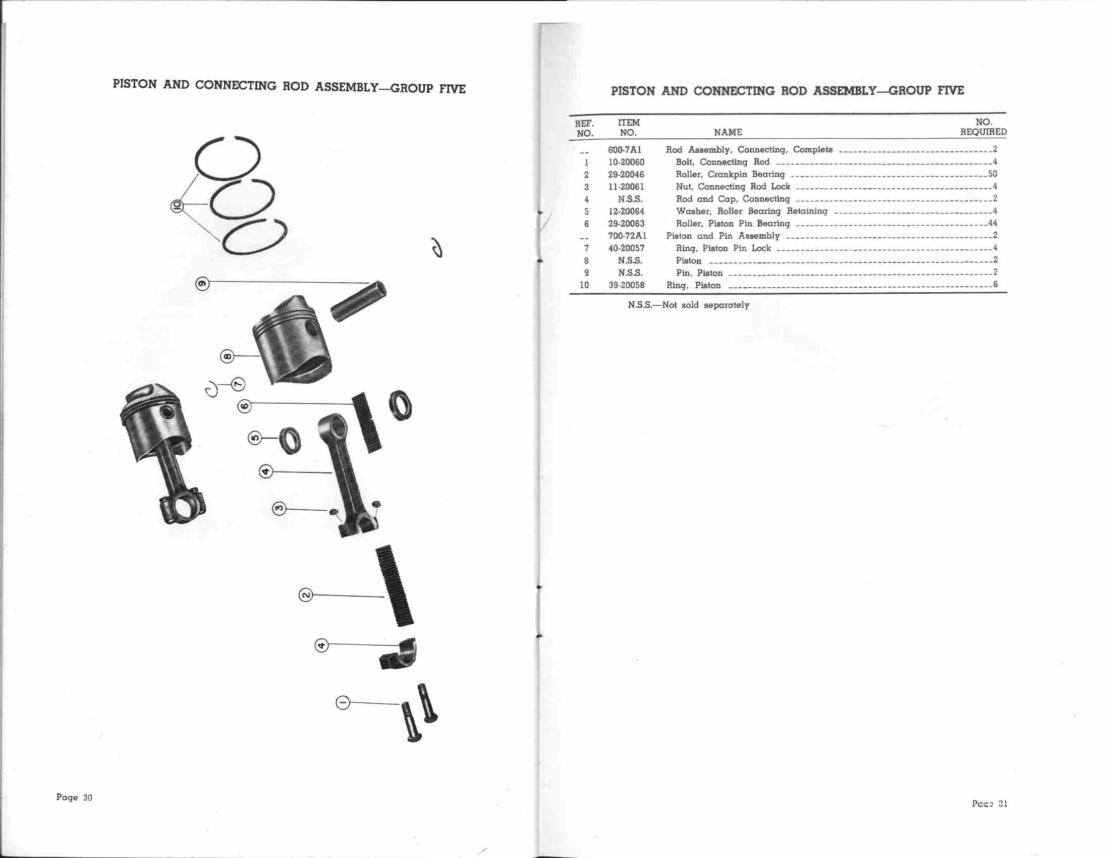
BALANCING RODS, PISTONS, PINS and SPACERS: This is where I made the biggest changes, the old pistons; rods, pins etc. weight was 470 grams each without the rings, I cut this down to 337 grams and here is how I did it. First I got a pair of three ring, round pin boss, super light mod pistons that were +.003 oversize to the old pistons. These pistons alone were each 37 grams less weight. Then I changed over to Mark 30 piston pins, these pins are closed on one end and are each 7 grams less each in weight. The rest was removed by balancing each part. Here is the procedure. The first thing I discovered was that the Mark 30 pin weights vary from here to there. The process I used to remove weight was using a carbide end mill to drill out the center of the pin in the lathe and then I removed more weight off the O.D. of the piston pin spacers just to get two of the same weight. This was quite difficult but when I completed this task, the new parts total weight for each assembly was 337 grams. The rod weight matched so I was very fortunate there. The 226 grams less weight in the rod and piston area should show an increase in horsepower out of the turns and higher RPM down the straightaway and much better response in all ranges.
MERCURY CONNECTING ROD OIL HOLE: Now this part of this procedure is my own idea and is NOT required. On my 20H when I disassembled it I noticed my piston pin spacers were too dark from heat build up. My previous experience building race car engines with floating pins suggested a change. The car engines have an added hole on the small end of the rod to eliminate this problem. This was not an easy procedure to add to the Mercury rods as they are heat treated to 50-60 Rockwell hardness. You must use a carbide end mill. I used a size .100 O.D. diameter end mill to put a hole in from the center of the I-beam on an angle through to the center of the piston pin hole. I then used a die grinder to chamfer the hole in a teardrop shape on the top I-beam side. You must be sure this hole is put in on the top side of the rods to the center of the pin hole because the oil will run down the hole to get more oil to the bearings at high RPM. I also loosen up the side clearance on the pin spacers on the pin from .011 to .020. This should eliminate "dark" spacers and after this procedure you MUST recondition your rods on a Sunnen rod honing machine.
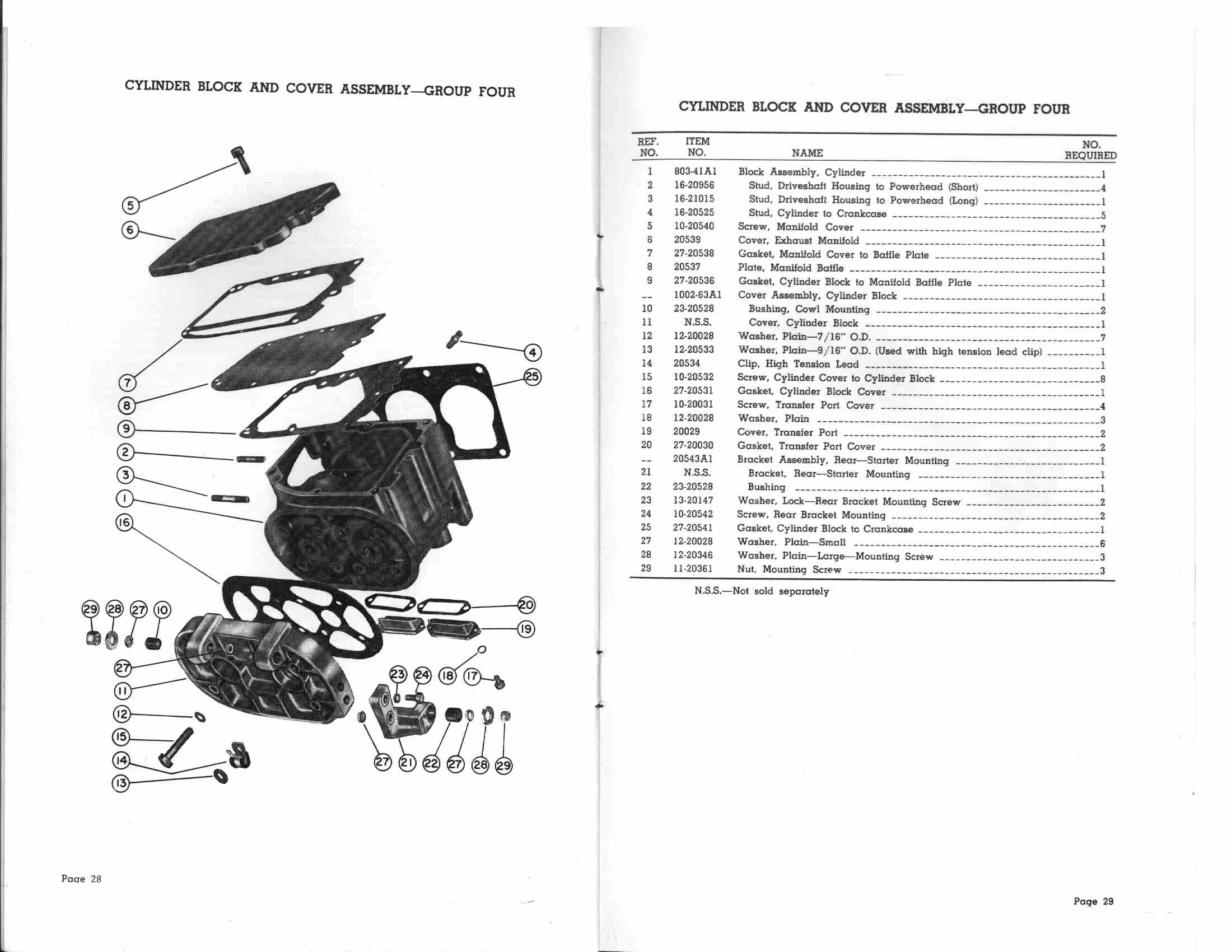
BLOCK WORK: This 803-41 block like the rest of the motor was as nice as you can get except for a small crack in the intake port. I mounted the block on a 5/8" thick plate to keep the block as straight as possible on the main gasket surface while welding the crack. After this procedure and letting it cool down I unbolted the block and checked the bores with a bore gauge and found like most motors with many hours on them the bores had a +.003 taper and were out of round from 2.438 to 2.4415. So by honing out the-block for the new lightweight pistons it should work fine for this motor. Before we hone out the block there is something else to take care of, the main block gasket surface was not flat. It had pull up at the studs .008 and the welding had moved it a little so to straighten it out I put the block up on the mill with the gasket surface up and indicated each bore in, then indicated the bore, top to bottom checking taper front to back and side to side. I had to shim the intake side +.003, this got my bores to run within .0015 on all sides (remember I have .003 taper). Now it is time to put in a big flycutter big enough to cover the block in one pass: I then clamp the block and shim and flycut the main gasket surface to 100% clean up. On my block it took three passes. A total of .011 was taken off to get this gasket surface perfectly flat (remembering that I had to take .006 of the crankcase earlier) a total of .017 was removed from this gasket surface. The gasket will make up for this much. Perhaps it might raise the compression somewhat but at least you can be sure that the block and crankcase are square to each other and this is very important .
HONING THE BLOCK: After doing some research on 2 stroke honing as to what you're really looking for in a good seal for a high performance 20H Merc, Oval F.Christner assured me that on a 20H stocker or gas mod or even an alky motor you always want to finish the cylinders with the very finest grit stones you can find! Also it is very important to "never" use a ball type hone or standard spring type 3 stone honing head on a high performance 2 stroke cylinder bore as both of these types of hones could cut 6 or more horsepower from your motor! It is strongly advised to use only a honing head that holds 4 stones with no wipers. These types of honing heads are very hard to find as even the Sunnen honing machine company only sells a 2 stone head with 2 wiper for even there most expensive type hoeing machines and this 2 stone head is not advised to be used on a 2 stroke motor. However, be advised there are honing heads made that will indeed hold 4 stones. The next thing you need to understand, regardless of what the piston ring manufacturer tells you about a finish for cast iron rings, O.F.Christner told me you "always" want as smooth a final finish on the bores as you can get as that's for sure horsepower! At this current time, Sunnen honing machine company sells a 800 grit stone however they also sell a 1000 grit, but that's a special order stone. The ultra light round boss pistons I am going to use in this 20H are +.003 oversize from my bores that I now have, so I will start offwith the block clamped on the Bridgeport table and use a indicator to dial in each bore center. Then use a coarse 400 grit stone in the honing head to straighten up the bores and to cut some stock out. My finished bore size will be for a total of .007 piston skirt clearance. The reason for this number is because these cylinders have that much taper in them to get 100% clean up for the rings to form new seal on.I used lots of honing oil with the rough 400 grit stones to flush out the bore as the stones cut the cast iron out to within .001 of my final skirt clearance. Then I checked the bores with a dial bore gage in many locations, top, center, and bottom of each bore and then with the new pistons. After checking this I found I was forced to shim the honing head to get the stones to cut the cylinders perfectly straight. After getting the bores true and to within .001 of finish, I changed the stones in the 4 stone honing head to a set of 800 grit and took the bores to the finish size. Unfortunately the bottom cylinder did not clean up 100%. It was about 97 % cleaned up but this was fine as I will be hitting each cylinder again just a touch after I fit the rings with the 1000 grit stones set up in a drill motor just before I assemble the powerhead so this operation is now complete. I then washed the block in solvent and wiped it down with outboard oil then bagged it up for now. FITTING RINGS: I got +.O15 oversize rings from Harry Brinkman. I had to file fit each one to each cylinder bore. The top rings I gave +.004 end gap, the second got +.005. I used the old rings in the third groove and they had about .012-.015 end gap. I used a special tool to bolt and cut the piston ring slot, it was quick and easy to use. After that, all I had to do was de-burr all sides and mark each ring for location and bore and bag it for assembly. SOME OTHER WORK: Before I start assembly there are two more things that I did to the motor for better exhaust flow out of the closed exhaust. First there is a stainless flat plate between the block and the aluminum exhaust cover plate. I cupped this-plate as much as possible towards the aluminum cover plate without letting it touch the aluminum plate. This was done to try and get the exhaust gasses to roll off this plate rather than to just hit it head on and try to somehow deflect off of it. The other thing I did was to smooth out all corners-in the exhaust area with a die grinder. This included all rough edges and parting lines in the casting, again trying to get the exhaust to roll out and down the exhaust housing as freely as possible for a straight shot out the back. ASSEMBLE THE MOTOR: First thing I washed the 803-41 block in hot soapy water three times, changed the water each time and then I blew off with compressed air and oiled the cylinders with outboard oil. All other parts were washed in solvent three-times, blown off and oiled, marked and bagged. The first thing to check is your end play of the crank and location of crank in the crankcase. Now I know how to check end play-and get it right, but the location of the crank in the crankcase has still got me confused so here is what I was told to do. I put a .003 bearing shim in the crankcase under the top bearing. I then pressed in the top needle and the big ball bearing. I then installed the crank without the reed block, pressed the new lower ball bearing in the case and installed it onto the crankcase and bolted it down (use-4 bolts) and tightened them to 10 ft lbs. While holding the crankcase steady I used a button indicator and base on the end of the crank. I then moved the crank up and back two times and took readings off the indicator. It read .0225 end play. I took the bottom bearing case off the crank and case and pressed the lower bearing back out. I installed a new lower seal and put two .010 bearing shims in under the new ball bearing and pressed together. I then re-installed on crank and case and bolted down to 10 lbs. The indicator was re-installed as before and the crank was moved back and forth again. Now it was showing .0025 and that is what I was shooting for in terms of clearance. This amount of end play is considered tight and if I were doing it again I'd allow for more end play. The factory recommends .008 to.0012 end play. The crank is now mounted on a stub- shaft in a vice. The center needle bearings were greased and installed with the outer race and clip, making sure the pin hole for the reed block was in the right spot to line up with the reed block. My reed valves looked perfect so I re-installed them with new bolts and tightened to specs. Next I Installed the reed block on the crank making sure the pin lined up with the center bearing race and tightened the two screws, all to specs of course. Just before I install the crank in the crankcase I got two 1/4-28 bolts just long enough to slip in between the throws of each with the nuts. I use this to keep the crank from bending while pressing the crank and reed block into the crankcase. I was fortunate to have use of a Mercury crank installation tool so I greased the crankcase and reed block, lined everything up and used the arbor press to install the crank assembly into the crankcase. The reed block hole lined up perfectly so I installed the bolt and tab washer, bent the tab and ran a dab of gasket sealer across the bolt and washer down to the crankcase. ASSEMBLY OF THE RODS AND PISTONS ON THE CRANK: Now this part of the procedure can he done in different orders but if you do it this way you can check the balance weight of all your parts as they are installed in the motor. This is why I choose to do it like this. I started by installing the small end needles in the rod with grease. I was able to find N.O.S. Mercury needles. These were then demagnetized before I installed them in the rods as were all bearings. Then came the spacers and a stub pin I made and the piston was held in place and I tapped in the piston pin and installed the snap rings after the shop made stub pin came out. I did this to both piston and rod assemblies. With this altogether I went back over to the scales to check each to make sure they were of equal weight and they were perfect, 342 grams each with bearing and snap rings. Now I am ready to install these on the crank. I used the new needle bearings (25) and new rod lock nuts and #721 red Locktite on the rod bolt threads and tightened the rod bolts to 17 ft lbs and checked this three times. INSTALLING THE BLOCK: After I had fit the rings in the block I observed some wear spots from fitting the rings in and out of the cylinders. So I touched up the bores with a hand held drill motor and a flex shaft 4 stone honing head equipped with 1000 grit stones to clean up both bores to 100% clean up on both. Then I again washed the block three times, hit the block with compressed air real good, dried off and wiped down with outboard oil. I also put more oil on the pistons after I installed the new rings on them. I installed the block studs, put a new crankcase gasket on between the block and case and used wooden paint sticks to push the new rings into each bore; one ring at a time. This is a tedious job and perhaps there is a ring compressor available for this operation. Next I rotate the crank until I can see the rings in the exhaust ports and I push on each one to make sure they have some end gap and then I bolt the block together and tighten. The next step is to take your flywheel and slip it on the crank taper minus the key, put some lapping compound on the tapered part of the crank and some in the flywheel tapered hole. Now hold the crank from turning and rotate the flywheel on the crank until you see a solid wear pattern on the taper of the crank, the flywheel is now lapped true. Clean all left over compound off the crank and flywheel. Now you are ready to install the new top crankcase seal from the top. Now install the flywheel and key in the crank and turn the crank over slowly by hand. (Flywheel torque spec. 65 ft.lbs.) Make a mixture of kerosene and outboard oil 50/50 and shoot some into the intake and exhaust ports every 6-8 revolutions to act as a flush to clean out small particles from the block and new rings. Do this procedure about 60-80 revolutions by hand then take compressed air and blow off all gasket surfaces -and wipe the motor clean. Now install the rest of the components, exhaust plate (1/4 20 screws, 80 in.lbs.), intake covers, ignition plate, back water jacket (50 in.lbs.), carb, brackets, timing handle, flywheel etc. until the motor is complete. Make sure you set your timing at a low setting and run the motor at this low setting for at least 1/2 hour running time before you start bumping the timing up. TO FIRE IT UP: I mixed one quart of outboard oil in one gallon of pump gas, after priming the fuel pump and carb I put a. shot of gas in the-carb, set the throttle at 1/4 opening and put the test wheel on the lower unit and dropped the 20H in the test tank. I had to crank it for awhile to get it to run. It was running on the top cylinder only but I ran it on that cylinder for about 10 minutes and shut it down for the day. The next day I pulled the outer case and recoil off, pulled the flywheel and found a condenser wire grounded-against the case (be very careful on this). Now only-three pulls were required to start this time to start. It sounded very weak and shaky at first but after approximately 30 seconds it smoothed out with lots of blue smoke. Please keep in mind I am only running Ľ of the timing I was running before the rebuild and. the one quart mixture to the gallon of gas. I ran the motor at low RPM always moving the RPM up or down and never letting it stay in one range for any length of time. I ran it for 10 minutes this way and then shut it down for over four hours to cool down to allow the new pistons and rings to conform to the block clearances. After that cool down I restarted and ran it for 30 minutes using the same procedure as before and then I shut it down for 2 1/2 hours. I then ran two gallons of gas through it with the timing still at Ľ advance. At shut down it would foul the lower plug due to these conditions. After this procedure was complete I raised the timing to 2/3 and cut the oil down to one quart to two gallons of gas. Again, I would run it in various RPM ranges. The motor was now starting to even out and show more power. The plugs were burning cleaner and have exhibited no plug fouling since, even though I have the high-speed jet set very rich. The next step was running it on the boat with the timing still at 2/3 advance and the oil mixture at 1 quart to 2 gallons of gas. I ran a 7 1/2-x 12 1/2 prop and dropped the motor way down on the transom. Now starting the motor and always running the RPM range up and down and after the motor warms up bringing it up on plane very gently. I cruised through six gallons of gas this way running up and down in the RPM range but never over 1/2 throttle. After this run the motor was beginning to feel much stronger. I then decided to change, to my speed prop and jack the motor up l 3/4 inches and to set the timing back to pre-rebuild full advance. On the next start up I experienced difficulty in restarting the motor at full-advance so I retarded the timing to 2/3 and it fired on one pull. Since the rebuild it does not like that much advance in timing. I ran another12-15 miles always moving RPM up and down, and then bring in more RPM up to about 3/4 throttle for another 25 miles. All is great so I keep moving up and testing for perhaps another 35 miles of running, bring it home and recheck everything. All is well and the plugs are burning just a little rich. Subsequent testing and it is still improving and runs smoother than it ever did. I am still running the high-speed needle rich. This motor is now running stronger and smoother than it ever did, exceeding any previous performance in acceleration or top speed. I would like to thank all the people who gave me their help on this 20H project. Harry Brinkman Dudley Malone
Ovid F. (Chris) Christner
Paul Christner
Addendum: 20H crankshaft specs. Top Roller Bearing Journal .937", Top Ball Bearing Journal .984", Ctr. Main Valve Bearing Journal .749", Connecting rod journal .880" early, later models .882", Bottom Ball Bearing Journal .984" Connecting Rod. Piston Pin .750", Crank Pin 1.137" Piston/Cylinder. (Std) O.D. above Ring Land 2.428", O.D. at Skirt 2.434", Cylinder Finish Hone I.D. 2.441" |